Central Process Unit (CPU) Socket Interconnect
CPU Socket Interconnect Key Technology Trends
Future CPU socket technology needs, especially for data center applications, should be driven based on key industry technology trends.
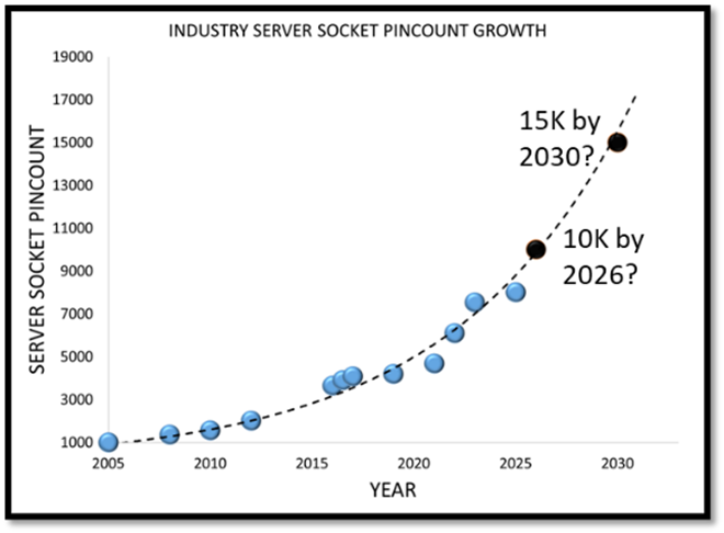
Pin count scaling: As seen in Figure 1, pin count trend over time is in an exponential trend. This exponential growth is being driven by an increase in total compute power, memory and input output (I/O) signaling bandwidth over the years.
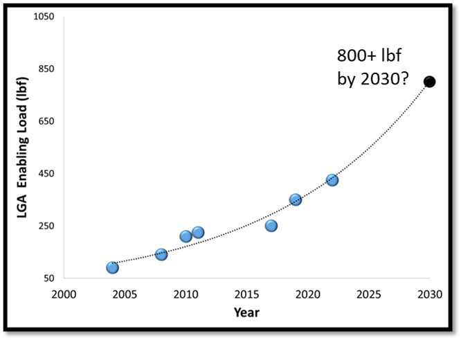
Land grid array (LGA) socket mechanical loading: With the exponential increase in pin count, there is an exponential increase in total mechanical load required to maintain higher signal fidelity and low resistance contact with the package as shown in Figure 2. This increase in load drives enabling hardware complexity, costs and more importantly, socket mother board keep out area, which could impact overall compute density per motherboard.
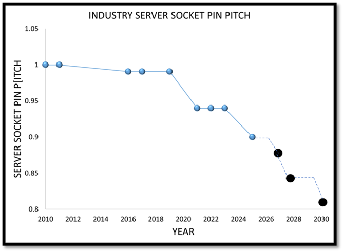
Pin pitch scaling: While the server pin count scaling is exponential, server socket pitch scaling is limited, as shown in Figure 3. Reduction in pin pitch is limited due to mother board type-3 printed circuit board (PCB) manufacturing challenges[1]. This limitation is driving bigger sockets and CPU packages, which could impact socket warpage, pick and placement and handling of the socket on the motherboard and during surface mount assembly.
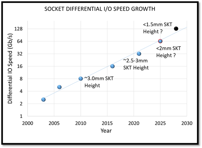
Increase in memory and high speed I/O data rates: There is an exponential increase in data rates, e.g., peripheral component interconnect express (PCIe) as shown in Figure 4. The data rate increase is forcing lower height sockets to meet high speed signaling integrity requirements. The reduction in socket height brings additional complexity to LGA pin designs to meet mechanical requirements as well as forcing higher warpage in sockets which is a potential interconnect issue at LGA to board interfaces.
Other considerations, e.g., per pin current carrying capability requirements also need to be considered to meet CPU die/package power delivery requirements.

Figure 1. Increasing memory and I/O bandwidth drives exponential increase in pin count

Figure 2. Pin-count scaling drives mechanical load driving enabling complexity, larger board keep outs

Figure 3. Server board pitch scaling limited by Type 3-PCB manufacturing/cost reasons which is driving bigger sockets

Figure 4. Exponential increase in data rates forcing lower socket height for low high speed signaling loss and impedance. (SKT=socket)
Technical Needs, Gaps and Solutions
The technology issues surrounding CPU sockets, the associated needs, technology status of those needs, as well as gaps and challenges to overcome, are summarized below. The time period considered is from 2024 to 2034.
Technology Status Legend
For each need, the status of today’s technology is indicated by label and color as follows:
In-table color + label key | Description of Technology Status |
|---|---|
Solutions not known | Solutions not known at this time |
Solutions need optimization | Current solutions need optimization |
Solutions deployed or known | Solutions deployed or known today |
Not determined | TBD |
Table 1. CPU Socket Interconnect Gaps, and Today’s Technology Status with Respect to Current and Future Needs
| ROADMAP TIMEFRAME | |||
TECHNOLOGY ISSUE #1 | TODAY (2024) | 3 YEARS (2027) | 5 YEARS (2029) | 10 YEARS (2034) |
Contact electrical performance | ||||
NEED | DDR5 PCIe Gen5 | DDR6, PCIe6 | DDR7, PCIe7 | 224 G/+ |
CURRENT TECHNOLOGY STATUS | Solution deployed | Solutions need optimization | Solutions not known | |
GAP | None | Contact design optimization | Contact design optimization CMT* LGA | New contact tech/optimization |
CHALLENGE | Contact height Contact mechanicals | Contact mechanicals Warpage control | Contact mechanicals SMT* LGA | |
Commentary: Data rates are doubling every generation. Need height scaling for low loss, low impedance socket interconnects (*CMT=compression mount, *SMT=surface mount, LGA=Land grid array).
| ROADMAP TIMEFRAME | |||
TECHNOLOGY ISSUE #2 | TODAY (2024) | 3 YEARS (2027) | 5 YEARS (2029) | 10 YEARS (2034) |
Contact pitch (mm) | ||||
NEED | 0.95-1.00 mm | 0.9 mm | 0.85 mm | 0.7-0.8 mm |
CURRENT TECHNOLOGY STATUS | Solution deployed | Solutions need optimization | Solutions not known | |
GAP | None | Contact design optimization | Contact design optimization, signal integrity | Type 4 PCB/HDI acceptance for server |
CHALLENGE |
| Server motherboard tech design rules/cost | Cost | |
Commentary: Server pin count scaling is exponential but pitch scaling is limited by type 3 PCB design rules, which drives bigger sockets, posing a challenge for overall server platform fit. Need to drive innovation in boards and sockets to scale pitch along with pick-and-place equipment and handling capability.
| ROADMAP TIMEFRAME | |||
TECHNOLOGY ISSUE #3 | TODAY (2024) | 3 YEARS (2027) | 5 YEARS (2029) | 10 YEARS (2034) |
Normal force (contact mechanical performance) | ||||
NEED | 25 gf | 20-25 gf | 15-20 gf | <10-15 gf |
CURRENT TECHNOLOGY STATUS | Solution deployed | Solutions need optimization | Solutions not known | |
GAP | None | Contact design optimization | Contact design optimization CMT LGA acceptance | New contact tech/optimization CMT LGA acceptance |
CHALLENGE | Contact height Contact mechanicals | Contact height Contact mechanical compliance | SMT LGA Low level contact resistance (LLCR) Signal integrity | |
Commentary: Pin-count scaling is driving higher loads. Need to drive lower per contact force to be able to reduce loads.
| ROADMAP TIMEFRAME | |||
TECHNOLOGY ISSUE #4 | TODAY (2024) | 3 YEARS (2027) | 5 YEARS (2029) | 10 YEARS (2034) |
Socket seating flatness: peak to valley warpage | ||||
NEED | 0.25 mm | 0.2 mm | 0.15 mm | 0.10 mm |
CURRENT TECHNOLOGY STATUS | Solution deployed | Solutions need optimization | ||
GAP | none | Mold material, mold design, modeling technology | Mold material, mold design, modeling technology | Mold material, mold design, modeling technology |
CHALLENGE | Socket body size | Socket body size, contact pitch | Socket body size, contact pitch | Socket body size, contact pitch |
Commentary: Server sockets are getting bigger and thinner. Need to control warpage to ensure package-socket mating.
| ROADMAP TIMEFRAME | |||
TECHNOLOGY ISSUE #5 | TODAY (2024) | 3 YEARS (2027) | 5 YEARS (2029) | 10 YEARS (2034) |
LGA ball coplanarity: peak to valley warpage | ||||
NEED | 0.25 mm | 0.2 mm | 0.175 mm | 0.15 mm |
CURRENT TECHNOLOGY STATUS | Solution deployed | Solutions need optimization | ||
GAP | none | Mold material, mold design, modeling technology | Mold material, mold design, modeling technology | Mold material, mold design, modeling technology |
CHALLENGE | Socket body size | Socket body size, contact pitch | Socket body size, contact pitch | Socket body size, contact pitch |
Commentary: Server sockets are getting bigger and thinner, with pin pitch shrinking. Need to control ball grid array (BGA) ball coplanarity for acceptable surface mount assembly.
| ROADMAP TIMEFRAME | |||
TECHNOLOGY ISSUE #6 | TODAY (2024) | 3 YEARS (2027) | 5 YEARS (2029) | 10 YEARS (2034) |
Contact current rating | ||||
NEED | 1.4 A | 1.5 A | 1.6 A | 1.8A-2.0 A |
CURRENT TECHNOLOGY STATUS | Solution deployed | Solutions need optimization | ||
GAP | none | Characterization methodology | Characterization methodology | Characterization methodology |
CHALLENGE | Pitch Height Current density | Pitch Height Current density | Pitch Height Current density | |
Commentary: With compute power going up, need higher current carrying capability per pin.
| ROADMAP TIMEFRAME | |||
TECHNOLOGY ISSUE #7 | TODAY (2024) | 3 YEARS (2027) | 5 YEARS (2029) | 10 YEARS (2034) |
Socket reseat functional contact defect | ||||
NEED | DPPM <500 (per pin) | DPPM <500 | DPPM <500 | DPPM <500 |
CURRENT TECHNOLOGY STATUS | Solution deployed | Solutions need optimization | Solutions not known | |
GAP | none | Socket flatness contact design | Socket flatness contact design | DC-LGA (dual compression land grid array) acceptance |
CHALLENGE | Pitch CPU Pad size Body size | Pitch CPU Pad size Body size | Pitch CPU Pad size Body size | |
DPPM = Defective parts per million

Figure 5. Examples of warpage measurement from Shadow Moiré and Finite Element Analysis (FEA) modeling[2]
Approaches to address Needs, Gaps and Challenges
Table 2 considers approaches to address the above needs and challenges. The evolution of these is projected out over a 10-year timeframe using technology readiness levels (TRLs).
In-table color key | Range of Technology Readiness Levels | Description |
|---|---|---|
2 | TRL: 1 to 4 | Levels involving research |
6 | TRL: 5 to 7 | Levels involving development |
9 | TRL: 8 to 9 | Levels involving deployment |
Table 2. CPU Socket Potential Solutions
|
| EXPECTED TRL LEVEL | |||
POTENTIAL SOLUTIONS | TODAY (2024) | 3 YEARS (2027) | 5 YEARS (2029) | 10 YEARS (2034) | |
TECHNOLOGY ISSUE #1 | |||||
Contact Electrical Performance | Lower height contact design (< 1.5 mm) | 2 | 5 | 7 | 9 |
Contact material | 3 | 5 | 7 | 9 | |
TECHNOLOGY ISSUE #3 | |||||
Contact Normal Force | Contact Material | 3 | 5 | 7 | 9 |
Contact design | 3 | 5 | 7 | 9 | |
TECHNOLOGY ISSUE | |||||
Socket Flatness | High Tg material | 1 | 4 | 5 | 9 |
Low coefficient of thermal expansion (CTE) material | 1 | 4 | 5 | 9 | |
Mold design optimization | 4 | 5 | 7 | 9 | |
TECHNOLOGY ISSUE #6 | |||||
Contact Current Rating | Mixed Contact design in the array | 3 | 4 | 5 | 9 |
Contact material | 3 | 5 | 7 | 9 | |
TECHNOLOGY ISSUE #7 | |||||
Socket Reseat | Tighter mechanical tolerance | 3 | 4 | 5 | 9 |
Lower system deformation | 3 | 5 | 7 | 9 | |
Summary
For current low pin count(LCP) materials, the CTE is not uniform, with the CTE about five times different between flow direction and transverse direction. This makes the socket flatness issues worse. Due to these non-isotropic characteristics, the injection molding tool design such as gate numbers, locations, molding conditions and housing part feature design can possibly be optimized to mitigate the flatness problem.
During the early socket development stage, FEA computer simulation and Shadow Moiré physical measurement can be helpful for better control of the flatness.
Dividing a large socket into 2 pieces or multiple pieces could also mitigate the warpage concern.
As socket height reduces over time, the material strength of the contact base metal needs to improve. This material strength improvement consideration is also correlated with socket flatness.
Under limitations of geometry and part design, certain optimizations can be done such as in material selection, socket manufacturability and pin arm length design versus signal integrity (SI) considerations. However, the requirement for the contact to be more compliant is not good for SI performance in general.
With higher power design requirements down the road, current density per pin will be increased to satisfy SI and power integrity needs. Different geometries and materials for SI and Power integrity are under research and development to satisfy these requirements.
References
Intel Xeon Processor Scalable Family, Thermal Mechanical specification and Design Guide, Dec 2019.
Ooi Renn Chan & Wendy Xu, “High Density Interconnect Socket Warpage Prediction and Characterization End-of-Project Webinar”, iNEMI Warpage Characterization and Management Program, April 2022, https://thor.inemi.org/webdownload/2022/Projects/HDI_Socket_Warp_EOP.pdf.
Board Assembly Acronyms
Return to Board Assembly Overview.
